![]()
![]()
![]()
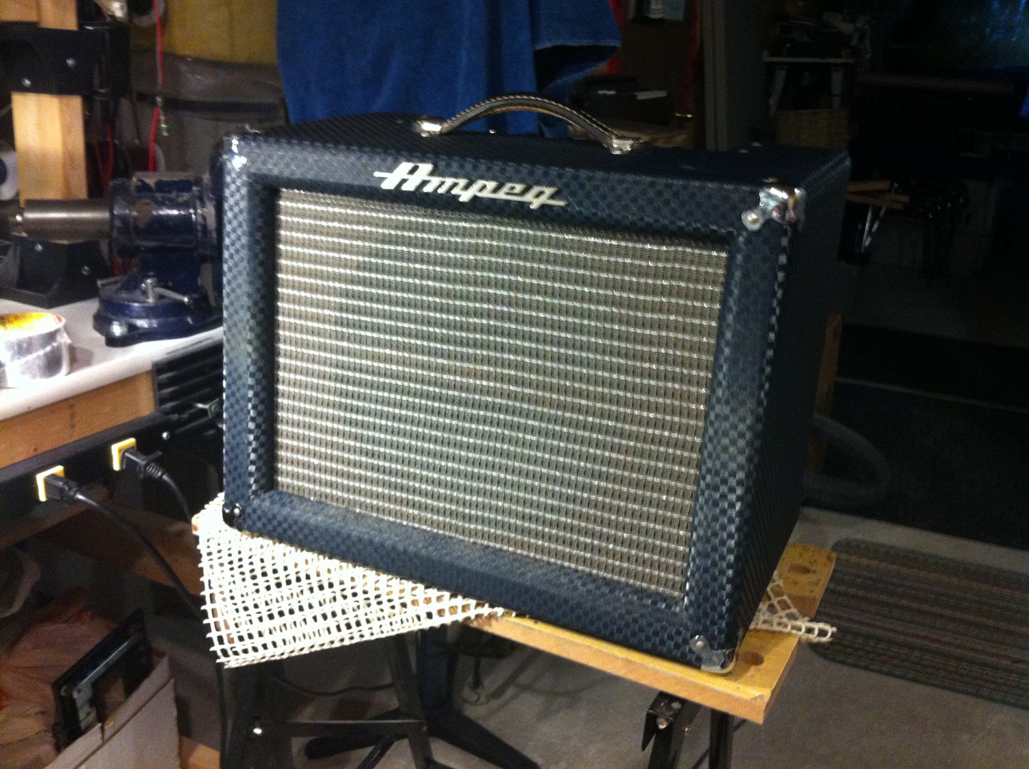
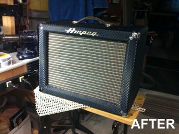
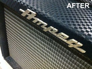
AMPEG J-12 A COMBO TUBE AMP (1964)
This amplifier is the Ampeg© J-12-A Combo Tube Amplifier (circa 1964) with one Rola 12" speaker, Tube Tremolo circuitry, two 6SL7 preamp tubes and two 7591A power tubes providing around 15 Undistorted Watts.
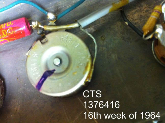
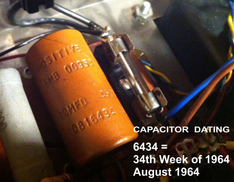
The year of manufacture was identified using info from Ampeg archives and the CTS pot date codes as follows...
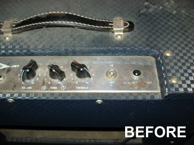
The control layout is simple; Volume Tone and Tremolo Rate. There is a power switch, green jewel ON indicator and the Rectifier is a 5Y3 Tube Rectifier negating the need for a standby switch (since it takes time for the rectifier to come up to full voltage allowing the heaters to become warm before full voltage is applied to the power tubes).
Since this amp is older than me, some service is required... performed as follows...
_________________________________________
SERVICE
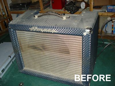
CLEANING THE AMP COVERING
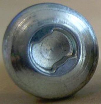
The amp was obviously subjected to living in a dusty garage and it was reported that the front speaker grille cloth was singed by a space heater tilted back against the amp. The Amp Cabinet was disassembled, deep-cleaned, and degreased. The Leather handle was like new after cleaning. The bolts on the cabinet chassis are clutch-head type and require a special screwdriver as not to damage the screws.
The Speaker Board was removed from the cabinet and the old burned grille cloth was replaced with new black/silver Ampeg grille cloth.
_________________________________________
CHASSIS CONTROL PANEL
The Chassis was removed from the cabinet, all of the knobs were removed from the front panel and the front panel was polished to a close-to-stock shiny appearance.
_________________________________________ REAR PANEL
After cleaning the rear panel, the Heat-Shielding film was replaced. The Schematic was in good condition considering that this amp was made in 1964...
A copy of the schematic is here...
_________________________________________ EXTERNAL SPEAKER JACK
A Rear-Panel 1/4" jack was added to allow the internal speaker to be disconnected from the amplifier and allow the use of an external speaker cabinet.
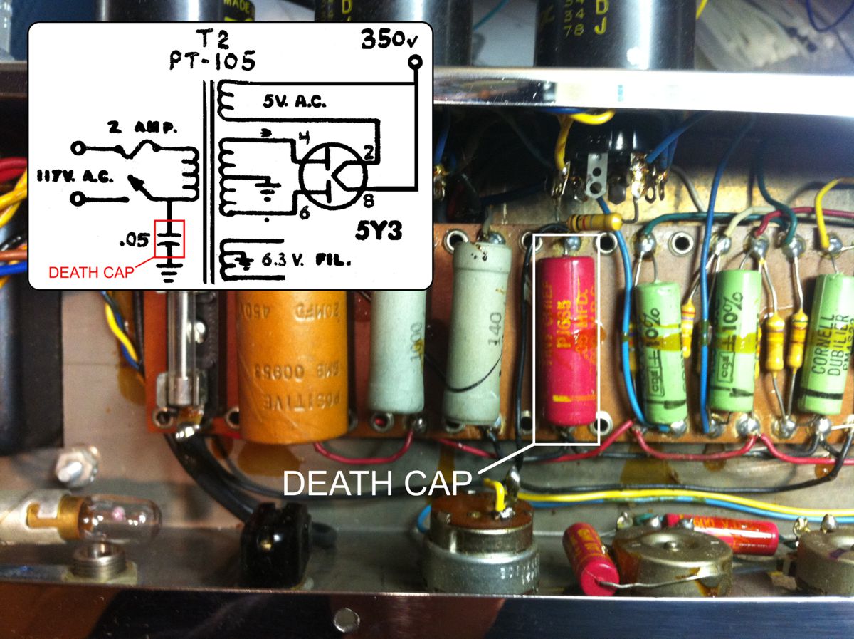
_________________________________________ REMOVING THE DEATH CAP
This amplifier was made safe by removing the 0.05uf capacitor from the line side of the transformer. The reason that this capacitor is dangerous is that if the capacitor ever failed and shorted, depending on which way the old two prong cord is oriented in the AC outlet, it can place line potential on the chassis which will possibly complete the circuit to ground through your guitar cord, guitar strings and your body.
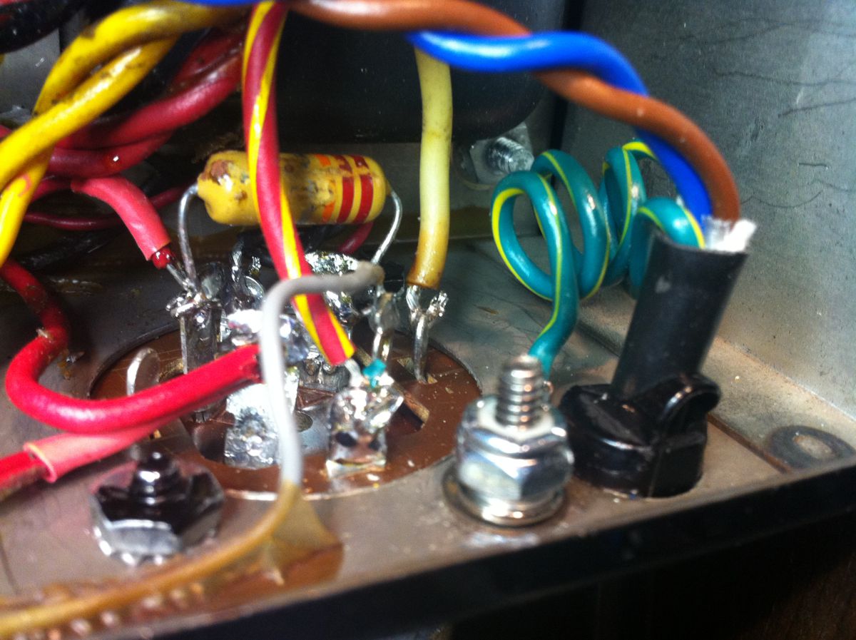
_________________________________________ ADDING A 3-PRONG POWER CORD
Just as removing the death cap protects the performer, installing a 3-prong power cord will do the same by shunting any line potential or high voltage from the tube circuitry, that hits the chassis, to ground. A new 3-prong cord was installed on this amplifier. The approved way of doing this is to drill a new hole for a chassis ground, as close as possible to where the power cord enters the chassis, and connecting the power cord ground wire to the chassis using the following sandwich... bolt, toothed washer, ground terminal, flat washer, lock-washer and nut. In this case the lock washer was substituted with a posi-lok nut that has an integral lock washer. It is required that the ground wire is longer than the two other conductors so that if someone trips on the cord, and the cord is pulled out of the chassis, if the live wire touches the chassis the live wire will be shunted to ground. Since the ground wire is longer, it will stay connected to the chassis until the live wire clears the chassis as it continues to be pulled out. Most likely the plug will be pulled from the outlet, but, it is better to be safe than sorry.
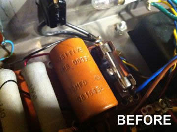
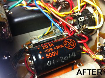
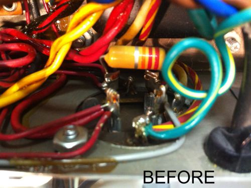
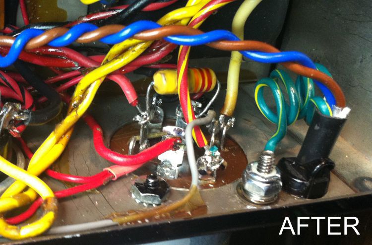
_________________________________________ REPLACING ELECTROLYTIC CAPS With any amplifier that is over 50 years old, the electrolytic capacitors have to be replaced... This is preventive maintenance as a cap failure could cause damage to other parts of the circuit... least of which is an annoying hum coming out of the speaker due to poor AC filtering.
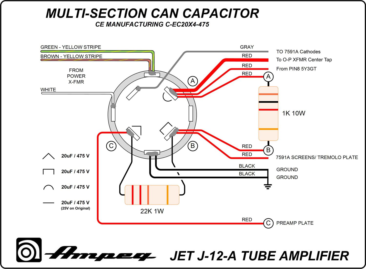
The main power Filter cap is a multi-section can-capacitor. It was replaced with a new CE Manufacturing capacitor with similar capacitor sections. Since there are many wires coming into and out of the cap, it was 'mapped' and many pictures taken to make it easier to re-wire the cap.
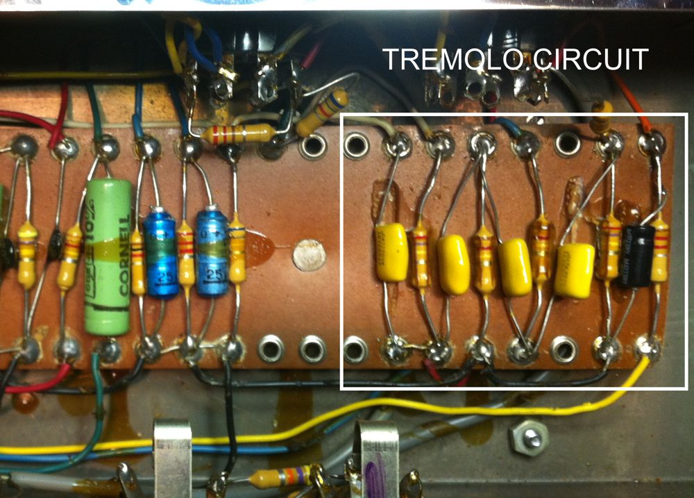
_________________________________________ REPAIRING THE TREMOLO CIRCUIT The previous owner reported a non-working tremolo circuit. I found that the stock tremolo circuit capacitors were replaced by someone, but, the tremolo circuit was still not working. In the process of troubleshooting the circuit I found that there was a short from one of the ground wires to part of the tremolo circuit. Probably from over-heating the eylet terminals... the ground wire insulation melted and made contact with part of the tremolo circuit. This probably happened when the tremolo caps were previously replaced. The shorted wire was routed away from the PCB and the tremolo, in its former glory, was working again!
_________________________________________
|